Archive for the ‘Cisco Security’ Category
Cisco’s EoS announcement for the ASA CX Modules and Cisco Prime Security Manager
How about that, 2 blogs posts in one day! However this is going to a real quick post so it shouldn’t count but hey there is a picture so it’s legit! I caught wind of this announcement on twitter late last night and just needed to put a small post about it. Mainly because some time ago I posted about the EoS announcement for the traditional IPS Modules, and I ended that blog post with the following question:

Well, that question has been answered. On 2/16/2015 Cisco announced the EoS / EoL timeline for the ASA-CX Modules as well the Cisco Prime Security Manager which was the management tool the CX-Modules. Along with same basic management functionality for the Cisco ASA Firewalls themselves.
Looks like the Official EoS date is 8/17/2015
With a final hardware support date of 8/31/202
You can view the full EoX timeline for the ASA-CX Module and PRSM here. The time line is too large for me grab in a single screenshot so I figure a direct link is the next best thing.
Control-Plane Protection & Control-Plane Policing
It’s not very common to see people jump on the idea of configuring Control-Plane Policing/Protection, a part of me thinks people avoid this subject like the plague because they feel it causes more problems then it is worth. Well, let’s be honest if you have had to troubleshoot a CoPP or CPPr policy you know it is fun process. Especially since checking the control-plane is not usually the first thing everyone looks at and half the time issuing a ‘sh run’ is just not an option at first.
The first thing we should probably clear up is, why should we protect the control-plane what is this going to do for us. Well let’s consider a few things the control-plane does:
- Handles packets that are not CEF switched, meaning the CPU has to take some time handle these packets.
- This is more important than you think, if the CPU is getting bombarded with a large number of packets the CPU must handle each one individually & it is possible the CPU will get too busy it start dropping other traffic.
- Maintains keep-alives for routing adjacencies.
- Handle traffic directed at the device itself
- SNMP/SSH, management traffic.
The control plane does a bit more then that but the three points above should get the point across.
The next thing I want to mention is how Control-Plane Protection (CPPr) differs from Control-Plane Policing (CoPP). Probably the main difference is the fact with CoPP you control access and limit access to the entire control-plane. This sounds good and simple but the control-plane is slightly more complex then that (go figure right). CPPr on the other hand allows us to control access to the individual control-plane sub-interfaces, providing us with more direct control. Here is a diagram from Cisco.com that lays out the control-plane:
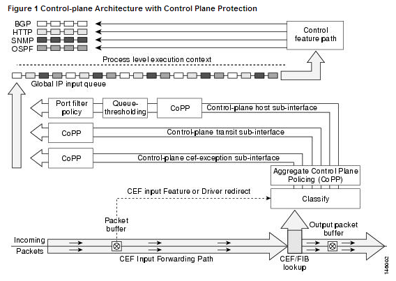
As you can see from the above diagram, applying a control-plane policy (CoPP) applies an aggregate policer to all traffic destined for the CPU. Reaching out of that aggregate you can see three addition sub-interfaces of the control-plane:
- Host – The host sub-interface handles traffic destined for the router or one of its own interfaces. IE: Mgmt related traffic and some routing protocol traffic. (EIGRP iBGP)
- Transit – This sub-interface handles software switched IP traffic. (I think also ICMP unreachable/redirects but I need hammer away at the ‘transit sub-interface’ a but more in the lab)
- CEF-Exception – This sub-interfaces typical handles non-IP related packets such as ARP, LDP, Layer 2 keepalives along with some routing protocol traffic. (OSPF eBGP)
Now, that we have an understanding of what the control-plane does for us, and the differences between CoPP vs CPPr let’s jump into some configurations. Luckily this configuration follows the framework of a typical QoS policy so if you familiar with the structure of the MQC you should be able to follow right along.
First we are going to create a few ACL’s to match our traffic:

Let’s put those ACL’s inside a few Class-Maps: (Only ACL’s, match ip DSCP/Precedence, & match protocol ARP are supported, hence why I did not do match protocol OSPF/BGP, if you do the command will get rejected upon trying to apply the service-policy to the control-plane)

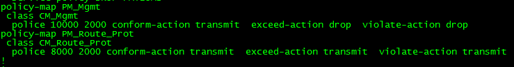
Now, we reference the Class-Maps within a Policy-Map and define our actions: (I’d like to make note, with a CPPr Policy-Map you can only use the ‘police’ or ‘drop’ actions)
Finally we apply a service-policy referencing the Policy-Map we just created.
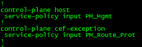
Now, that applies a CPPr policy to two different control-plane interfaces, if you simply want to perform CoPP you could do the following:

Combine our two separate policy-maps from before

Apply the Policy-Map to aggregate control-plane
Notice the console message, that CoPP has been enabled on the aggregate path. The CoPP policy shown in the above two pictures just about accomplishes the same thing as our CPPr Policy (With a few exceptions I want you to point out).
A look at Flexible Packet Matching and a possible use case?
Flexible packet matching, definitely an extremely powerful tool and a complicated one at that, not only because of it’s configuration but also because you need to be familiar with the different protocol structures as well as regular expressions if you want perform some fancy matching criteria.
In a nutshell, Flexible packet matching allows routers to look deep into a particular type of packets, & into the various fields contained within the packet to perform specific actions based on the contents of those fields.
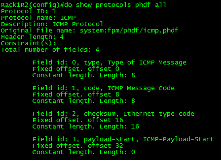
Before you can configure flexible packet matching, you will first need load a PHDF, Protocol Header Definition File. The PHDF is an XML file that outlines the format of the protocol header, the name of the fields, the length of the fields, and where the fields start within the packet. Below is sample of the XML text with the icmp.phdf:

To dwell on the PHDF for a bit longer:
- The field name matches a particular field within the header for the most case.
- The offset, denotes where the field starts in the packet header. The offset is always from the start of the header.
- The length, defines how long the field is.
- Notice the length and the offset can either be in bits or bytes
- The total length of the header at the bottom of the PHDF is also a requirement.
- This is all good to know since you can create your own PHDF files.
Here is a quick outline of an ICMP packet so you can correlate the PHDF to the to the actual packet.

To load the PHDF file itself, you’ll want to issue the following command:

After the PHDF is loaded you can issue the following command to see the specifics of the PHDF file itself. Similar to what is listed in the PHDF file itself.
Next, we are going create an ‘access-control’ class-map to match our traffic. I will keep the example to ICMP for simplicity:
![]()
Notice, we have multiple match statements, making sure we only look ICMP Echo packets, that have have a number with the first 256 byes of its payload. Now remember you can get pretty creative with regular expression, (If you’ve done any real work with BGP routing policies you know what I mean) for the sake of this post I wanted to keep it simple.
Now we need to create a ‘stack’ class-map, this particular type of class-map allows the router to narrow down its matching criteria by matching particular protocol headers in a particular order. If you do not specify a ‘stack’ class-map the the ‘IP’ header will be assumed. The example below matches ICMP over IP. Check out the INE link at the end of this post to see an advanced ‘stack’ involving ICMP within an IP-IP tunnel.
![]()
Since we have the ‘stack’ and ‘access-control’ class-maps defined it is now time we tie this together within a policy-map. Before we do that, we need to create an ‘access-control’ policy-map to match our ‘access-control’ class-map, and define our action when matching traffic is seen. There are only a few different options with ‘access-control’ policy-maps. (All of the pretty much listed below)

To tie together, the ‘stack’ & the ‘access-control’ class-map we will need to create another ‘access-control’ policy-map referencing the ‘stack’ class-map as a class, and then referencing the class-map containing our action as a service-policy.
![]()
With all the pieces tied together now, we can apply this to an interface:

So now, any ICMP Echo packets with a digit from 0-9 in the payload will get dropped, we can verify this by issuing the following show command:

Not an easy process, and quite a tedious one in fact. So what could you possibly use this feature for? Well this feature could be used as a psuedo-IPS to block a specific set of malicious traffic, or even to block ICMP Covert channels without the use of an IPS.
Here are some other resources for Flexible Packet Matching:
INE FPM Article – Great resource for showing off the power of FPM, by matching ICMP packets within an IP-IP tunnel
I highly recommend the Wireshark WCNA book for learning about the different protocols headers (and much more)
Unicast Reverse Path Forwarding uRPF
Another great security feature within every Cisco IOS ISR is uRPF, Unicast Reverse Path Forwarding. This nifty little feature has the router verify the source of any IP packets received is reachable via the routing table. uRPF is used to prevent common spoofing attacks and follows RFC 2827 for ingress filtering. The router will actually rely on the CEF table to perform lookups. uRPF works in 2 modes strict mode and loose mode, lets quickly talk about these two modes of operation.
- Strict Mode: In this mode the router verifies the source of the IP packet arrives on the same interface the router would use to reach that source address. Beware of asymmetric routing.
- Loose Mode: In this mode the router simply verifies the source IP can be reached via the CEF table using any interface.
Now that we quickly discussed the 2 different modes uRPF operates in, let’s go over a few quick tips:
- Since uRPF relies on CEF, CEF must be enabled.
- uRPF takes into account multiple paths, so if you are doing any equal cost load sharing uRPF will take that into account. uRPF will also take into account any unequal cost load sharing (such as EIGRP variance).
- Asymmetric routing is different from (un)equal cost load sharing, and can/will cause issues with uRPF.
- uRPF works best at the network edge, and to further specify the network edge not on your access layer the network edge facing the public internet.
Let’s now configure uRPF, we are going to start off with the configuration of loose mode:

This is a good time to mention uRPF is configured on an interface basis, and it is enabled by a single command. The keyword at the end of the command specifies the mode uRPF operates in, since I am configuring uRPF in loose mode I want to make sure the router can reach the source of any IP packet received on interface fa0/0 using any interface on the router.
Now let’s configure uRPF to operate in strict mode:

You’ll notice this command is very similar to the way enable loose mode, with the exception of the keyword rx at the end of the commend, this tells the router to verify the source of any IP packet received on interface fa0/1 should be reachable via interface fa0/1 and not any other interface on the router. As mentioned previously the router verifies connectivity by looking at the CEF table, if CEF points to an interface that the packet was not received on that packet will get dropped.
Now that we have configured uRPF (simple right?) let’s issue a couple show commands to verify our configuration:
Show ip traffic – This command will tell you how many packets uRPF has dropped.

Under the IP statistics the first Drop section has an entry for unicast RPF this counter keeps track of how many packets uRPF drops which is definitely useful to know. You’ll also notice 12 packets were dropped, which we will discuss later.
Another command is show cef interface %Interfacenum/num% this command will also tell you whether or not uRPF is enabled on the specific interface.

Let’s also not forget the simplest command of them all: show run interface %interfacenum/num%

One feature that makes uRPF even more powerful is the fact we can tag on an ACL specifying traffic we want checked or don’t want to be checked. For example I configured uRPF on one my lab routers that had an old DMVPN & BGP configuration running on it, shortly after I configured uRPF I noticed the BGP adjacencies to the spokes go down. After that I configured an ACL so my DMVPN Tunnel traffic was not caught by the uRPF check.

You guys should know by now how much I love named ACL’s but you’ll notice I used an extended numbered ACL, the reason for that on the is simply due to the fact I couldn’t use a named ACL with uRPF.

No option to use a named ACL only numbered ACLs. There are two other options there allow-default which allows the default router to be used when verifying source addresses, and allow-self-ping which allows the router to ping itself, although allowing self-ping opens the router up to a DoS vulnerability.
You can also read more about uRPF in RFC 3704.
Configuring TCP intercept.
SYN floods are a pretty common DoS attack that can be performed on any TCP based (FTP, Web Server, Email, etc) application over the internet, luckily our normal run the mill Cisco IOS ISR routers have a feature known as TCP Intercept that can protect your servers from this type of attack.
TCP Intercept operates in 2 different modes but the overall concept is the same, TCP intercept will take into account every SYN packet from the client that traverses the router and if the connection remains half-open or there are so many half-open connections the router will start sent sending rest (RST) packets to close that connection. Half-open connection are those that do not fully complete the TCP handshake (SYN, SYN-ACK, ACK process).
The first of two modes that TCP Intercept operates in is intercept mode. In this mode the router actually accepts the SYN and responds to the source with the SYN-ACK packet, if the client completes the connection by sending the ACK the router then passes the original SYN to the destination and negotiates the connection with server, the client is completely unaware this process is even going on. The only thing to keep in mind with the intercept feature is that the router only keeps track of the TCP packet type, it does not take into account any TCP options within the packet (ie: window scaling or other TCP features within RFC 1323).
Here is a diagram of the process (This image is from Cisco Press: Cisco Router Firewall Security’s book)

TCP Intercept in Intercept mode capturing every SYN packet and acting as buffer protecting the server behind.
TCP Intercept can also operate in a watch mode in this mode the router takes a much more passive approach. In this mode the router does respond to any SYN packet it just sits back and watches the TCP handshake process. If the router notices a connection is half-open for so many seconds it will send a RST packet to the server so the server closes the half-open connection.
Now that we have an understanding of TCP Intercept let’s go ahead and configure TCP intercept.

TCP Intercept configuration options
TCP intercept is configured from global config mode and we have quite a few configurations options here. I’m going to configure TCP Intercept for both watch and intercept mode and we will go through the configurations:

Sample TCP Intercept watch mode configuration
This watch mode configuration accomplishes the following:
- Sets the TCP Intercept mode to watch mode. ip tcp intercept mode watch
- TCP Intercept is configured to monitored TCP connection to servers matched in the TCPInterceptACL access-list, this provides us granular control of the servers and ports we want to monitor. ip tcp intercept list TCPInterceptACL
- The router will transmit a RST packet to servers if the connection is not established within 8 seconds. ip tcp intercept watch-timeout 8
- TCP Intercept will enter an aggressive mode and start dropping the oldest TCP connection if there are 500 half-open TCP connections until that number is below 400 half-open TCP connection. ip tcp intercept max-incomplete high 500 & ip tcp intercept max-incomplete low 400
- TCP Intercept will enter an aggressive mode and start dropping the oldest TCP connection if 300 connection requests within one minute until that number is below 200 requests a minute. ip tcp intercept one-minute high 300 & ip tcp intercept one-minute low 200
- TCP Intercept will close and any connection that has been open for 8 hours (28800 seconds) with no activity. ip tcp intercept connection-timeout 28800

Sample TCP Intercept watch mode configuration
The above TCP Intercept intercept mode configuration is very similar to the previous watch mode but the first thing you will notice is the fact it doesn’t tell you it is operating in intercept mode, this is because it operates in intercept mode by default. You also notice 2 additional commands in here:
- ip tcp intercept finrst-timeout 20 this tells to router when it sees a TCP connection being torn down, if that connection is not closed within 20 seconds the router will close the connection itself by sending a RST packet.
- ip tcp intercept drop-mode random when TCP Intercept starts aggressively dropping connections by default it drops the oldest connections, this behavior can be changed so the router drops random TCP connections instead of the oldest connections.
You can verify how TCP Intercept is interacting with your traffic by issuing the following commands:
- show ip tcp intercept statistics – This will give you a quick look at incomplete, established, & how many connection requests have been made to the servers matched by the ACL.
- show ip tcp intercept connections – This command shows you all the current connections TCP Intercept is working with/watching.
- You can also use debug ip tcp intercept to quickly see what TCP Intercept is doing in real-time.
Now if you want to fully lab this feature out and see it in action you can set up a client/server enviroment in your lab and either configure an ACL to block ACKs from your source client or use a program call Scapy to transmit SYN packets.
Sample ACL:
access-list 101 deny tcp host hostaddress eq portnumber host destination ack
Sample Scapy SYN packet:
sr1(IP(dst=”destinationIP“)/TCP(dport=destinationPortNumber,flags=”S”))
Configure your router to watch for login attacks.
Even though we can configure SSH for secure management, this still does not stop a random person from connecting to your device in an attempt to guess the password. In some cases this could be a bored user who is just curious or in worst cases it could be a malicious user trying to perform a dictionary attack on your password. Something we can do is to configure our router to start blocking login request after so many failed attempts occur within a specific time frame. Now this isn’t going to secure your router indefinitely but it is a simple preventative measure they will slow down any real dictionary attacks and will most likely discourage any bored employees in hopes that they lose interest or remember they have other work to do.
So now let’s say we have an existing router with SSH enabled and we want to configure this login block feature, well let’s enter the following command:

Yep one command. This will block all logins for 120 seconds when 5 failed attempts occur within 60 seconds of each other. Below is a breakdown of the block-for command, and notice all the timers are in seconds.

Now when the router notices these failed attempts it enters a “quiet mode”. This quiet mode is what tells the router to block all further login attempts until the timer expires.
So now I hit my router with a bunch of invalid attempts and noticed the following error get logged:

This message states quiet mode is now on and also notice it actually logs the username I attempted to log in as (ss in this case), the source of the login attempt (192.168.1.109), the port I connected on (22 default for SSH), and the reason (failed login authentication)
From this point I cannot even connect to the router over port 22, putty flat out tells me the connection is refused:

The following error message will also get logged when I attempt to login to a router that is currently in quiet mode:

Stating our login attempt has been blocked by an ACL, but wait we didn’t configure an ACL on this router. Let’s check the VTY lines:

We didn’t configure this ACL but the login block feature did. The cool thing about this is when “quiet mode” is turned off the ACL dissappears:

Pretty cool right? We have now taught the router to protect itself.
While this is a nice feature to have configured the last thing you want is to find yourself locked out of your own equipment. So what we can do is configure the router to accept login attempts even when quiet mode is enabled, while that might sound counter-productive to this whole feature it will be something you definitely want to do.
And we do it this way:

The first thing I did was create an ACL (SSH_MGMT) that permits my management workstation (or management subnets) and then I issue login quiet-mode access-class command and reference the ACL I created. This tells the router to accept login requests from the hosts allowed within the quiet-mode ACL when quiet mode is on and the router is blocking login attempts from everyone else.
So now when quiet mode is initiated this custom ACL is applied to the line VTY lines:

You can verify your configuration with the show login command, this provides you a nice summary of what has been configured as well as the current state of the router:

A few things to keep in mind:
- While the quiet mode ACL will allow login attempts from hosts matched in the ACL, those very same hosts can trigger the router to enter quiet mode.
- If you already have an access-class assigned to the VTY lines and quiet mode kicks in, the quiet mode ACL will be applied during the block-for time. However when the timer expires the quiet mode ACL is removed and the original ACL back in place.

