Archive for the ‘Cisco Wireless’ Category
Why link latency is important for Cisco lightweight access points.
Link latency, it’s a convenient little check box you turn on individually (or globally) on lightweight access points (Operating in FlexConnect/H-REAP or OfficeExtend) to see the latency details to the controller, while this is one of those ‘yea that’s nice to know’ type things it can be a key resource when troubleshooting certain WLAN issues.
First lets start with why knowing the latency is important, well Cisco has published the requirements for CAPWAP latency from the LAP to the controller and that requirement is no more than 300 ms of latency. Now while most enterprise’s do not have to worry about those latency requirements too much (due to a typical MPLS, VPLS, or metro backbones) other types of companies that lets’s say rely on a pretty common DMVPN over the Wild West (the Internet) may have to keep in mind these latency requirements. If you do not meet these latency requirements you might be seeing CAPWAP packets drop in transit or your Flexconnect/H-REAP LAPs flapping between ‘Connected’ mode and ‘Standalone’ mode which depending on your setup can cause a host of issues.
Link latency will monitor the following:
- The round trip time of the CAPWAP heartbeat, it does this by comparing the timestamps of when the request is sent to when the reply is received. Now, by default this CAPWAP heartbeat occurs every 30 seconds and this CAPWAP latency is different from normal network latency, as the CAPWAP heartbeat also has a dependency concerning how quickly the controller can process the request and send the reply back out.
Something to keep in mind about the link latency stats, is the fact they do not reset unless the LAP reboots or they are manually cleared so if you decide to turn on link latency come back 6 months later and review the states you are not going to get any useful information.

Configuring and viewing Link Latency
As you can see from the above screen shot link latency will provide you a quick glance of the current latency, minimum latency, and the maximum latency to the controller. (From when link latency was first enabled or last cleared)
Knowing the different Cisco LAP modes.
It’s been a while since my last wireless post, and surprisingly I never done a post regarding the different modes a Cisco LAP can operate in. I figured this would be a great place to start up my wireless posts again!
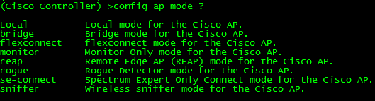
Now depending on the model access point you are working with and which IOS you are running you may or may not be able to operate a LAP in all the modes I will be describing:
Local: Probably the most common and well-known mode a LAP operates in mainly because this is the default mode a LAP will operate in (Unless you are running Flex controllers). In local mode, the LAP maintains a CAPWAP (or LWAPP depending on your IOS version) tunnel to its associated controller. All client traffic is centrally switched by the controller which why LAPs have been referred to as ‘dumb’ APs, primarily due to the fact it does very little thinking on its own. As a matter of fact, if a LAP operating in local mode loses its connection to the WLC, the LAP will stop forwarding and begin looking for the controller. Until the LAP (operating in local mode) joins another WLC it will not forward any user traffic.
REAP/H-REAP/Flexconnect: This mode has certainly evolved over the years and certainly deserves multiple posts of its own. REAP stands for Remote Edge lightweight Access Point and is there to address the scalability issues with Local mode after all it is completely unfeasible to place a WLC at every branch location. If you had every LAP operating in Local mode and you experienced a WAN failure at the location housing your WLC, every LAP in your network would stop forwarding user traffic, crippling your wireless networks. LAPs operating in REAP mode do not always require a connection to the WLC, and have the capability to locally switch WLAN traffic without relying on the controller. The functionality of REAP was later expanded to H-REAP (Hybrid-REAP) getting a littler better with each code release. Later on H-REAP was later re-branded again being called Flexconnect gaining a host of new features.
Bridge: Bridge modes have been around a long time, and as you would expect allows you to bridge together the WLAN and the wired infrastructure together.
SE-Connect: SE-Connect mode allows you to connect to the LAP using Cisco Spectrum Expert and gather vital information about the RF spectrum surrounding the LAP. Do keep in mind a LAP operating in SE-Connect mode will not be broadcasting an SSID and does service any WLAN clients. This mode is strictly used for troubleshooting purposes.
Sniffer: Similar to SE-Connect mode, a LAP operating in Sniffer mode is strictly for troubleshooting purposes. Sniffer mode will passively monitor the surrounding WLAN environment (Over a specifically configured channel) and tunnels all the 802.11 WLAN traffic to an end point on your network (configured by you), where you can use protocol analysis tool (Wireshark, Airopeek, etc) to review the packets and diagnose issues.
Rouge Detector: Again similar to SE-Connect & Sniffer mode, Rouge Detector mode does not service any WLAN clients. Rouge Detector mode connects to your wired infrastructure usually over a trunk link and watches the traffic traversing the VLANs. The LAP in Rouge Detector mode is watching for any MAC addresses that other LAPs have marked as a wireless ‘rouge’ device. Think of this as a tag team match up, your LAPs operating in Local or H-REAP/REAP/Flexconnect modes are passively watching and reporting rouge APs and rouge WLAN clients, while the LAP in Rouge Detector mode is watching the wired network for the MAC addresses of those same rouge APs and rouge WLAN clients. It’s there to be an extra layer of security in the event your users connect rouge APs, you use a Rouge Detector LAP detect and alert on those events.
Configuring the AP mode can be from the CLI of the WLC using the following command: config ap mode %AP Mode% %AP Name%
Control roaming behavior on your Cisco wireless network.
Roaming is just another expectation from your end users. They expect to walk freely around the office to conference rooms or far off cubicles and have their laptop or handheld remain connected while downloading files or in the middle of a conversation. If the roaming process is not quick enough then you could see conversations and clients gets dropped forcing them reconnect to the WLAN, and I can guarantee you your end users will be calling.
Now, if you have done a proper site survey and have solid data to work off of, you can control the roaming behavior of your WLAN clients. The reason you need to know the details of your wireless environment is because you are going to set RSSI limits concerning when your clients should begin looking for a new AP to associate to and, how quickly they are roam between access points. Just keep in mind, making these settings will effect the entire WLAN not just individual sections.
I would also like to mention your clients should be CCXv4 or higher to take advantage of these features. To see if your clients are CCXv4 compliant go to Monitor -> Clients -> click on the client in question.

On your Cisco Wireless LAN Controller, you want to navigate to Wireless -> 802.11a/n or 802.11b/g/n (depending on which frequency you want to customize) -> Client Roaming.

The first thing you need to do when you want to customize these settings is change the mode to custom this will allow you to edit the default values for the rest of the parameters.
The next option is minimum rssi. If a clients RSSI value is below this threshold it will not associate/authenticate to the access point, instead it will continue to look for a better signal from different access points. Valid values for this field are -80 through -90. The understanding is that the signal strength/quality will be so low reliable communication will not be established.
Next we have a setting called hysteresis this value is in dB and states how much stronger the signal of another access point has to be before a client decides to roam to it. This is useful if you have multiple access points in close proximity of each other or clients are moving between the edge of coverage of different access point. The higher this value the closer a client needs to be to an access point for it to associate to the second access point. Valid ranges are from 2 through 4 dB.
Now we have the scan threshold this is another RSSI value range. When the wireless client’s RSSI drops below this threshold the client will begin actively scanning for another access point it can receive a stronger signal from. Valid values range between -70 through -77.
The last field on the page is the transition time this is the amount of a client is going to see a better signal from neighboring access, before it attempts to associate to the second access point. The client determines a better signal when its RSSI drops below the scan threshold and it sees a signal from a neighboring access point higher than the scan threshold.
So all these factors do work together and can be customized for your environment. Normal data traffic is more forgiving since it’s not as delay sensitive, but If you have voice on your WLAN you will want to fine tune these settings to avoid dropped calls.
Cisco IOS DHCP Server with Option 43 for LWAP’s
Cisco routers (and switches) have the ability to hand out DHCP addresses, so if you have a relatively small branch office & you don’t want to set up a full DHCP server you can simply add that functionality to your Cisco device.
It does take quite a few lines to get this going but I wouldn’t consider it to be a complicated configuration, each parameter is pretty self-explanatory. Let’s look at a typically IOS DHCP configuration.

Now the first thing you want to do is define the DHCP pool with the ip dhcp pool poolname command this puts us into (dhcp-config)# mode where we can configure addition parameters for this pool. Next you see the network 192.168.20.0 255.255.255.0 command which defines our DHCP range followed the default gateway, DHCP lease duration (3 days in this case), the DNS Server the for the DHCP clients, and finally the domain name.
The next thing we are going to do is configure some DHCP exclusions, these are simply addresses we tell the DHCP service not to hand out. We are also going to change the amount of times the router pings an address before it declares the address available.

Now the exclusions are done from (config)# mode (but as you can see they can be entered from (dhcp-config)# mode) along with the ip dhcp ping packets 4. The Cisco device will ping an IP address within the pool to see if it available, by default the device will send 2 pings if they both time out it assumes the address is available, here you can see I changed it to send 4 pings.
You can view any DHCP leases by issuing the Sh ip dhcp binding command. (Yes I know the time is a bit off but this my lab switch)

Now for some bonus content, I was going to split this up into multiple posts but figured I would just roll it in.
We are going to configure Option 43 in our DHCP scope. Option 43 is vendor specific, and is used by Cisco LWAPs to find and join WLC controllers. It’s all done in the following line:

As you can see this is also done within the DHCP Pool at the (dhcp-config)# configuration mode. The tough part here is figuring out the hex value however the hex value consists of 3 parts. The first part is the type which is always 0xF1, followed by the length which is the number of controller management IP address times 4 (So if you have 2 controllers for redundancy it would be 2 x 4 = 0x08), the third part consists of the ip addresses of controllers management interface in hex. (Now seriously did you ever seeing yourself converting IP’s to hex, or did you use a hex calculator?). For this example I used 2 management IP addresses 192.168.2.5 which is C0A80205 in hex and 192.168.3.5 which is C0A80305 in hex. Now all that together gives us the f108C0A80205C0A80305 hex string seen the above configuration.
Now here’s a DHCP packet with the Option 43 field:
 Now packet analysis can be a bit daunting at first, but if you go line by line, you can easily make out everything that was configured, you see the option number and the hex value we entered, now your LWAPs in branch offices will be able receive a DHCP address and still find your WLC’s.
For more information on setting up a Cisco device as a DHCP click here. (This guide goes much more in depth then my post)
For more information on DHCP Option 43 and Cisco LWAP click here.
Cisco WLC Interfaces.
If you have ever worked with a Cisco WLC or have looked through any configurations for a WLC, then you have no doubt seen the interfaces that make it work. You’ve probably also seen that diagram concerning how these interfaces relate to the physical interfaces on a Cisco WLC.

Now their are only five different types of interfaces (Management, AP-Manager, Virtual, Service-Port, and Dynamic Interfaces), I figured I would just take some time to quickly touch on them.
- Management Interface – As you can suspect this interface is for in-band management and handles any communication with AAA servers. This interface will also handle the layer 2 communication between the controller and any APs. Needless to say the configuration of this interface is mandatory and can not be skipped.
- AP-Manager – If you want to have APs on different subnets other then the subnet the WLC is on then this interface must be configured, it’s a requirement for Layer 3 LWAPP transport mode. So as you would suspect this interface handles all layer 3 traffic between the WLC and the APs. Since higher end WLCs can have multiple AP-Managers only 1 AP-Manager interface can be configured per physical port.
- Virtual Interface – Another mandatory interface that must be configured (once again like the management interface you don’t get the option to skip the configuration of this interface). This interface handles any mobility management, VPN Termination, Web authentication, and is also a DHCP relay for WLAN clients. You really want to give this interface a bogus type address (Like 1.1.1.1 or something) since it’s only accessed and used by the WLC, the APs and WLAN clients will not interact with this interface. (Other then it’s purpose as the DHCP relay, but it’s all in done within the controller unknown to the AP’s or clients)
- Service-Port – This is also a physical port for out of band management, so it’s configuration is optional. The port doesn’t even support 802.1Q, so you can’t use it for anything other then accessing the controller. (Note: This is only physical port that is active while the controller is booting)
- Dynamic Interface – Now these are the interfaces you can create and use to link specific SSID’s to specific VLAN’s on the wire. So this is where and how you can separate your wireless client traffic, this interface will also double as the DHCP relay for it’s subnet/VLAN (Note: A WLC can have up to 512 dynamic interfaces)
Cisco WLC redundancy with mobility groups.
While LWAPs and Wireless Controllers can streamline and standardize WLAN deployments, it also tends to provide a not so nifty single point of failure. If you only have one WLC in your network and you lose all connectivity to that WLC, whether it be a mis-configuration or a general failure all your LWAP’s will go down until they can join the controller again (or find another controller to join).
The configuration for this is actually fairly simple (especially if you only have 2 WLC’s). First off you want to issue the sh mobility summary to go over the current mobility settings, all these settings are important but probably the most important one is the Default Mobility Domain this is the current name of the mobility group and both controllers will need to be in the same mobility group. (Important: Mobility group names are case-sensitive). If you wish you can change the mobility domain name by issuing the follow command config mobility group name group_name command.
Now once you’ve decided on a mobility group name and both controllers are in the same mobility group, you need to add each respective controller’s MAC address and IP Address as a member of the mobility group on all participating controllers. This done with the following command config mobility group member add mac_address ip_address. Mobility group members can be removed by changing the add keyword with the word delete. Now, each model of Cisco WLC’s can support a max number of 24 mobility group members. So their is a limit, albeit a fairly large limit but it does exist.
Also keep in mind, all this can be done via the GUI interface under Controller -> Mobility Management and of course in the GUI everything is pretty self-explanatory in labelled fields for you to configure easier. (Just more time-consuming)
Once this is all said and done you want to issue the sh mobility summary again to verify the configuration and verify the status of each mobility group member is up.
A few facts to keep in the back of your mind are mobility group messages communicate over UDP port 16666, you will want to create rules or an ACL allowing that kind of traffic between the controllers (If you have any type of firewalls between them). You can issue the following commands to very connectivity ping, eping, mping. Obviously the ping command is just there to verify layer 1 connectivity, eping will verify the EoIP tunnel between the controller has formed. The EoIP (Ethernet of IP) tunnel is where all these mobility messages are exchanged through, and mping will test communication over UDP 16666.
Cisco.com resources
WLC Configuration Guide Release 7.0, Chapter 14 Configuring Mobility Groups
Note: I would have loved to include my own screen shots, but I do not have 2 WLC’s out of production to work with.

