Archive for the ‘CCIE’ Category
Let’s Review: EIGRP Named Mode
My next stop on my CCIE: R/S Written review. EIGRP, the big change here is EIGRP Named Mode it’s the same EIGRP with a new shiny cover. So , let’s jump in.
To start the new named mode configuration we need to define the ‘named instance’ compared to defining the autonomous system out of the gate.

Now, we are dropped into router configuration mode, with a new set of configuration options

From this configuration mode, we can turn on/off the EIGRP instance, configure the address family instance and service family instance. However, from this top layer I do not see the option to configure the advertised prefixes or alter metric information. So lets dive a bit deeper and look at the address family configuration. (If you have done anything with MP-BGP, you’ll know where this is going:

Looking through the address family configuration options, we start seeing options that we are familiar with. First off we decide if this will be IPv4 or IPv6, then we can decide on the autonomous system, whether this is a unicast or multicast address-family, and the last cool thing VRF specific details!
Once we define the IP version and AS #, we get dropped if in a new configuration mode, where we get into some more of the nuts and bolts:

Notice from here, we can define what interfaces participate in this EIGRP Address Family, along with some metric information and we can define specific neighbors (POP QUIZ: How does statically defining neighbors affect the behavior of EIGRP?)
Some of these configurations take us deeper down the configuration-mode rabbit hole, for example configuring the af-interface goes down another level. In this next configuration mode we can define interface specific options such as summary routes, BFD, timer intervals, and much more:

What about route filtering and redistribution, so far we haven’t seen a way to do that yet. This is where the topology base command comes in:

Now, the picture is becoming complete. From this topology configuration mode we can perform some route-filtering, redistribution, and even apply offset-lists to further manipulate routing metrics.
So the configuration is quite different than the old method but at least now it is all contained in one spot in a more hierarchical model.

Another, fun fact. You can migrate the old EIGRP syntax to the new named mode configuration with the following command: eigrp upgrade-cli
Let’s Review: OSPF LSA Types
With my Written exam for CCIE: R/S coming up soon (Cisco Live 2015) I figured this would be a good time to back over some basics, and when it comes to OSPF what is more basic than OSPF LSA Types!
LSA Type 1 – These are also known as Router LSA’s, every router participating in OSPF will generate one of these, and Type 1 LSA’s are flooded within the area that the router belongs. So, what is it the Type 1 LSA tells us:
- Certain capabilities, is the router a Border router or ASBR. (Respective E-bit and B-bit)
- Does the router terminate a virtual link (V-bit)
- Number of links
- Link types – PtP, Virtual, etc
- Link Cost/Metric
So lot’s of good information in LSA-1, think of these as a ‘blue-print’ of the router, describing what is has and what it is doing.
LSA Type 2 – Network LSA’s. These LSA types are generated by the DR (Designated Router) and one type-2 LSA is generated for every network with two or more OSPF neighbors. You can expect to find these when you multiple devices connected to a broadcast network (A.K.A. LAN) or on an NMBA network (Frame Relay/DMVPN). Type-2 LSA’s will include information about the attached routers along with information of the network segment. This LSA is just an informative one, letting you know what other Routers you are connected to along, no metric/cost information is included in a Type-2 LSA.
LSA Type 3 – Summary LSA’s. Type-3’s are generated by ABR’s and are used to extend reachable to other OSPF areas. Remember LSA Type-1’s are limited to the area that they originate them in. They also designate Inter-Area connectivity as opposed to Intra-Area connectivity. A good rule of thumb is for every route in the routing table, there should be an associated Type-3 LSA in the OSPF LSDB.
LSA Type 4 – Think of these as Type-3 LSAs however instead of being generated by ABRs they are generated from ASBRs. Type-3 & Type-4 LSA’s use the exact same format, however the differentiating factor is the fact, a Type-4 Link State ID is the Router-ID of the ASBR. (Where-as a Type 3 LSA will/may have a Link State ID of the IP Network)
Similarities in Type-3 & 4 LSAs
- Cost/Metric information is included in these LSAs (unlike Type-2 LSAs but those do serve a different purpose)
- Contain routing prefix/host information for reach-ability purposes.
LSA Type 5 – AS-External LSAs. Type 5 LSAs are also originated by ASBRs and represent external routes from another Autonomous System (or routing protocol) typically done via redistribution. Type-5 LSAs will contain metric/cost information similar to that of Type 3s & 4s, however because this information external from the OSPF routing domain there is some additional information included within this type of LSA.
- External Metric (E-bit) – Designates the external metric of the route. Used for Type-2 External routes, where as Type-1 external routes do not include this information (IE: Set to 0, so the field is included just the value is set to 0)
- Forwarding Address – Specifies where transit traffic should be sent, in some cases this can be (intentionally) set to all 0’s in which case the forwarding address will be that of the Router-ID of the originating router.
- Route Tag – Used to set tagging information of the route itself (typically for mutual redistribution purposes). 32-bit field.
- Remember redistributing static or connected routes also generates Type-5 LSAs, the routes do not always have to originate from another routing protocol.
LSA Type 7 – External LSAs, only found when using NSSA Areas (Not So Stubby Area). So if Type-7 LSAs are only found in NSSAs then how does this reach-ability information make it to other areas? Well the NSSA Border router will translate these Type-7 LSAs to Type-5s for the rest OSPF network/Areas, this is designated by the P-bit / Propagation bit.
Back to studying I go!
Private VLANs when, where, & how.
Recently PVLANs came into a design discussion, which in turn led into me reminiscing on my Route/Switch days. So naturally when I wanted to re-visit the topic if anything to make sure I still remembered everything what was important and to see if any features have been added with the new IOS’s. It’s been a while since my last PVLAN deployment so here we go!
Terminology:
- Promiscuous Port – This is the ‘primary’ VLAN that can communicate with all the other Isolated & Community ports with the PVLAN environment.
- Isolated Port – This is a ‘secondary’ VLAN that will only communicate with the ‘primary’ promiscuous VLAN. Isolated ports cannot even communicate with other isolated ports. Since we are talking about VLANs, communication is blocked at the Layer 2 perspective. (At which layer do VLANs operate at, Layer 2)
- Community Port – This is another type of a ‘secondary’ VLAN, like Isolated ports a community port can also communicate with the ‘primary’ promiscuous VLAN. The big difference here is that a port configured in a ‘secondary’ community VLAN can also communicate with other ports configured as community ports. They will not however be able to communicate with ports configured in an ‘isolated’ VLAN.
Traffic Flows:
Since these Private VLANs operate at layer 2 it is worth pointing out some specific traffic flows, after all it is worth considering the implication of this isolation and typical broadcast/multicast flows:
- Broadcast Traffic
- The promiscuous port will forward broadcast traffic to all isolated & community ports. (Including trunks)
- The Isolated port will only forward the broadcast to a promiscuous port. (Including trunks)
- Community ports will forward broadcast to the promiscuous & other community ports. (Including trunks)
Configuration & Topology:

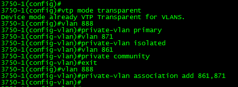
- The configuration is not too bad, you’ll notice the first thing we do is set the VTP to transparent mode. If you are running VTP v1 or v2 this needs to be done.
- Next we create a VLAN like normal, however under the vlan configuration, we set the PVLAN mode. Here we are setting VLAN 888 to be a ‘primary’ promiscuous VLAN.
- Next we create VLAN 871, and designate it as a ‘secondary’ isolated VLAN
- Followed by us creating VLAN 861, and marking is as a ‘secondary’ community VLAN.
- Once we finished creating our ‘primary’ & ‘secondary’ VLANs we need to associate our ‘secondary VLANs’ to our ‘primary’ VLAN.
To re-cap, we set the VTP mode to transparent, created and assigned out promiscuous VLAN along with creating and associated our isolated & community VLANs, not too bad right?
Now that our VLANs are defined lets map these Layer2 private VLANs to a Layer-3 SVI:

So there, we created the SVI for VLAN 888 (The primary VLAN) and we associated the ‘secondary’ VLANs to the SVI with the private-vlan mapping add command. You’ll also notice the system message stating that our mapping was successful.
Now, that we have Layer-3 mapping lets go ahead and assigned a few ports to our private VLANs.

Here we, enter interface fa1/0/20, set the switchport mode to private-vlan host and configure port 20 to be an isolated port. (By placing this port in the isolated PVLAN)
Port fa1/0/21 on the other hand is configured to be in the ‘community’ VLAN.
Next, we are going to configure Port Fa1/0/22 to be a promiscuous so it can communicate with ports in both VLAN 861 & 871:

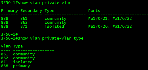
Verification:
Verifying the PLVLAN configuration is simple enough:
show int private-vlan mapping – Verify your Layer2 to Layer3 mappings

show int switchport – Verify Layer2 switchport parameters

show vlan private-vlan – Verify PVLAN setttings & ports.
New page is up, CCIE: Data Center study links.
Well it has been a crazy week for me and unfortunately I have not even had the time to put together a proper blog post.
To keep the information flowing I have added a new page to my blog “CCIE Data Center Study Links“. For the last 9 months or so I have been very data center focused, and I am planning on tackling the CCNP: Data Center certification soon (Probably going to be taking one those exams at Live this year). During that time I’ve gathered quite the collection of links & videos for data center material. Recently, I thought to myself instead of keeping this information locked in my own Evernote account I should move this to the blog. So there it is!
So far I have only been able to consolidate some of the Nexus material I’ve used, the new CCIE Data Center Study Links page will continuously be updated. (So keep checking back!)
CCIE: R/S Written Passed!
Finally knocked out the CCIE: R/S Written Exam!! The countdown has begun I’ve got 18 months to go pass the lab or I’ll be taking the written again!
If you’ve been following I’ve been studying for the CCIE: R/S for around a year now so the trek continues!
Now back to Cisco Live I go!!
The lab is ready to go!
Well, with the exception of a console server I got all my routers racked, stacked, and cabled!

It’s all cabled and ready to go! I got the following:
4x Cisco 1841’s
2x Cisco 2621xm’s
2x 2610xm’s
1x 2620xm
2x 3750’s
2x 3560’s
1x 3745 -This is going to get a NM-32a modules for the console server.
Aside from the lab equipment I got:
1x SonicWall TZ210
2x 2960 switches
And, I still got 2U left in the rack not sure what to fill that space up with yet. I was thinking of some old 2950G’s or maybe a Cisco ASA. I also picked up the INE workbooks last week so I here goes nothing!

