Archive for 2012
When does the Cisco ASA IPS module inspect traffic?
Sure we can put an IPS module inside an Cisco ASA firewall but the first you may ask or will be asked is at what point does that traffic get inspected by the IPS Module? Which might not seem like a tough question but it can make you think if you got VPNs terminating on your ASA, does it inspect the traffic before encryption, after encryption, or is encrypted traffic bypassed? I did a post about the packet flow through a Cisco ASA some time ago and it did mention the IPS is involved after NATs, application inspection, and even ACLs however there was no mention of how encrypted VPN traffic.
Well, as it turns out the traffic is redirected to the IPS module after it enters the ASA on the ingress interface, the VPN traffic is decrypted, and the firewall inspection policies have been applied. Now for outgoing VPN traffic the IPS inspects that traffic and then it is encrypted and sent through the IPSec connection. Makes perfect sense.
Here is a quick visual from Cisco.com:
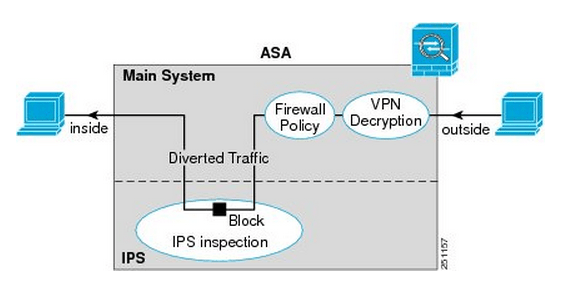
You’ll notice once the traffic enters from the outside interface, if it is VPN traffic it is then decrypted sent though the firewall policies and is then diverted to the IPS module. Once the IPS module has had a chance to inspect the traffic it is then sent back to the ASA to be sent out the inside interface.
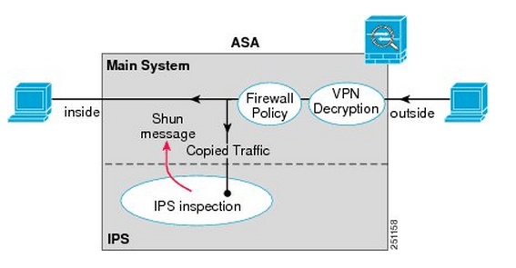
Something I want to point out the IPS Modules work in 2 different modes, inline mode which is shown above where the traffic is sent through the IPS module and back into the ASA this mode may degrade throughput depending on the model of the module and the amount of traffic being inspected. We also have Promiscuous mode where the traffic is not sent directly though the IPS Module but the IPS module instead receives a copy of the traffic to inspect. The upside of promiscuous mode is the fact throughput is not effected however it is less secure than inline mode since the traffic sent to its destination at the same time it sent to the IPS module, the IPS module however can sent a RST packet ending connection or ‘shun’ the offensive IP address. When an address is ‘shunned’ any traffic from that source is dropped.
Here is a quick visual of promiscuous mode:
You can read more about the IPS ASA module inspection process here.
Checking out IPv6 addressing.
IPv6 definitely a subject that is being pushed more and more as time passes, with good reason it’s the way the internet is moving. I’m not going to cover the history of IPv6 and why we are going to start seeing IPv6 becoming more and more prevalent as time goes on, but we will take a quick high level view of some of the major differences of IPv6 addressing for example:
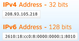
The address format, as we are well aware of IPv4 address are 32-bits long broken up into 4 octets that are 8-bits long. This format has been accepted so everyone is comfortable writing, memorizing, and understands this format.
IPv6 addresses on the other hand are 128-bits in length making it near impossible to continue the decimal format we all know and love in IPv4. That’s why the IPv6 address are represented as 32 Hex characters (compared to 128 decimal characters). This 32 character hex IPv6 address is then broken down into 8 sections of 4 hex characters separated by colons. So if we take a closer look at this break down each of those 8 sections represent 16-bits, and 16*8=128, so each individual character within the IPv6 address represents 4-bits and 32*4=128, so hopefully this paragraph clarifies the reasoning of why IPv6 address has been formatted this way. 32 character hex addresses will be easier to work with than a 128 character address. (Granted shifting gears from decimal to hex formatting will be tricky enough in itself).
So with this new address format, the next question you must have is how do we subnet with IPv6 addresses. Luckily for us subnetting (along with route summarizing) is done just like it is done with IPv4, granted with IPv6 we will be summarized in hex and not just decimal numbers. I’ll cover summarizing IPv6 in a future post.
Lets also touch quickly of the different type of addresses, perhaps the biggest change here is the fact that IPv6 has done away with the broadcast any IPv6 communication will be one of the below:
Link Local: The link local address is designated as FE80::/10 and will exist on every IPv6 interface the important thing to remember about the link local address is the fact it well never be used to communicate with hosts outside that local subnet, the link local address is only used for communication on its local subnet. This link local address is also used by OSPFv3 and EIGRP to establish neighbor adjacency and will be used as the next hop address.
Anycast: A new type of address, in which the same address is assigned to multiple nodes, when a packet is destined to this anycast address it will routed to nearest member of the anycast group.
Multicast: Treated similar to how it was treated in IPv4, and One-to-Many communication. (Multicast functionality has been improved upon since its implementation in IPv4). The key difference between Anycast and Multicast is the fact that the packet will be delivered to every device in the multicast group, where-as the Anycast packet is only delivered to the nearest device with the Anycast address assigned to it and not to every device with the Anycast addressed.
Even though these IPv6 are 32 hex characters we do have a few ways to cut down on the size of the actual IPv6 address to make it a little easier:
1. Leading zero’s can be removed so 2001:0db8:85a3:0042:0000:0000:0370:7334 could be typed as 2001:db8:85a3:42:0:0:370:7334 which helps by cutting out a few numbers but there is still another way we can make this address a bit more manageable.
2. Consecutive zero’s can excluded so 2001:db8:85a3:42:0000:0000:370:7334 could further be summarized to 2001:db8:85a3:42::370:7334, however this rule can only be used once so you can exclude one set of consecutive zero’s
Video: Configuring HSRP
Put together a quick video about configuring HSRP and many of its features: Tracking, Preemption, tweaking timers, changing priorities, and more.
Let me know what you guys think, this is the first video and I am still looking at different recording software or just different styles in general. You’ll be seeing more of these videos as time goes on!
An overview of SNMP,
Simple Network Management Protocol (SNMP), it’s a protocol that has been around for a long time and exist across the board on networking devices, servers, firewalls, UPS, and just about any other device you can name that we use in the IT field. It’s a standard management protocol defined by IETF for managing devices.
Their have been a few different versions of SNMP over the years, starting with SNMPv1 however short comings were discovered with this implementation the most notable being its lack of security. Then came SNMPv2c which is backwards compatible with SNMPv1 however SNMPv2c offers more security than its predecessor however I feel security is still lacking in SNMPv2c. The newest implementation of SNMP, SNMPv3 offers both Authentication and Encryption providing SNMP with the level of security it deserves.
SNMP relies on 3 pieces a
- NMS– Network Management Station, this is the device that collects the SNMP information from the networking devices it is managing.
- Managed Device– This is the device that is being managed by the NMS.
- Agents– An agent is the application that runs the SNMP process and contains all the local management information on the managed device.
Now the NMS gathers its management information by sending request to the manged devices and the managed device responds with the desired information. The follow packet types are used with SNMP:
- GetRequest -Sent by the NMS to the managed devices asking for the managed device for information.
- SetRequest -Also sent by the NMS to the managed devices, asking the managed device to change its configuration or a value.
- GetNextRequest -Again sent by the NMS to the managed devices where the NMS is requesting additional information from a previous request.
- GetBulkRequest -Introduced in SNMPv2 as a replacement to the GetNextRequest.
- Response -Sent from the managed device to the NMS in response to a GetRequest, SetRequest, GetNextRequest, GetBulkRequest or InformRequest.
- Trap -Sent from the managed device to the NMS containing local system information.
- InformRequest -Sent as an acknowledgement to a Trap.
I like to think of the SNMP agent as an internal database that keeps track of the local managed device. This “SNMP database” is a structure composed of MIBs (Management Information Base), and each MIB contains a value that value is called an OID (Object Identifier). This structure is commonly referred to as a “tree” due to how it is represented, here is an example:

Each of those boxes represents a MIB and within those MIBs are groups of OIDs, each one containing information regarding the status of processes, interfaces, fans, power supplied, batteries, and many parts of the particular device. Something I really recommend (if you have not done it already) is walk the MIB tree of a few devices there are many free applications out there that perform MIB walks, just keep in mind there are some MIBs/OIDs that can be found on every devices but once you get past the standard MIBs every device different and memorizing MIB trees and OID values is near impossible but as long you understand the concept and know how to find what you need, you’ll be ok. Many vendors provide their MIB structure online on their website making finding particular OIDs very easy.
For further information you can see the following RFCs
The lab is ready to go!
Well, with the exception of a console server I got all my routers racked, stacked, and cabled!

It’s all cabled and ready to go! I got the following:
4x Cisco 1841’s
2x Cisco 2621xm’s
2x 2610xm’s
1x 2620xm
2x 3750’s
2x 3560’s
1x 3745 -This is going to get a NM-32a modules for the console server.
Aside from the lab equipment I got:
1x SonicWall TZ210
2x 2960 switches
And, I still got 2U left in the rack not sure what to fill that space up with yet. I was thinking of some old 2950G’s or maybe a Cisco ASA. I also picked up the INE workbooks last week so I here goes nothing!
Cisco Express Forwarding – CEF
In my last post about unicast Reverse Path Forwarding, I made quite a few references to CEF. CEF (known as Cisco Express Forwarding) is a feature built into every Cisco router and is enabled by default it’s really the feature that makes Cisco well Cisco. I figured I would take a little time and discuss CEF in a little detail.
From a 500 foot view CEF is a method the router uses to forward packets, without utilizing any CPU cycles. CEF builds 2 cached tables in memory, these 2 cached tables are built from every entry in the routing table. So when the next packet arrives the router simply looks up the CEF entry found within memory to forward the packet, compared to sending the packet to the packet to the CPU for a route lookup and then forwarding the packet on.
CEF works by creating two tables:
- The Adjacency table maintains the layer 2 forwarding information for each FIB entry eliminating the need for the router to send out ARP requests.
- The FIB (Forwarding Information Base, also known as the CEF table) contains information from the routing tables and tracks the next-hop for all routes. So where the adjancency table manages layer 2 information the CEF table manages the layer 3 forwarding information
Now that we know the components of CEF, lets talk a little about how CEF interacts with packets as they enter the router.
- Once the packets arrives at the router the layer 2 information is stripped off. (This is normal and happens whenever a frame is accepted to a layer 3 device)
- Next the router looks up the destination using the CEF table.
- Then the router finds the corresponding adjacency table entry.
- The router then adds the corresponding layer 2 information (found in the adjacency table) back to the packet and forwards the packet on. All from memory.
You can view the CEF table by issuing the command sh ip cef:

Now remember the CEF table is layer 3 information so we have destination prefixes and what the next hop address is along with the outgoing interface.
You can view layer 2 adjacencies by issuing the sh adjacency %Interface% detail:

Since the adjancency table pertains to layer 2 information we’ll see some MAC addresses here, one thing I want to point is that long hexidecimal number in the fifth line that line consists of the destination MAC address of 10.1.1.2, the source MAC address of this routers fa0/0 interface and the ethertype of 0800 (Meaning it’s an ethernet interface)
Now this was only the tip of the iceberg for CEF, and this post was only supposed to bring it to light on a real high level so more CEF related posts will mostly surface as time goes on.

